Light glyph lamp
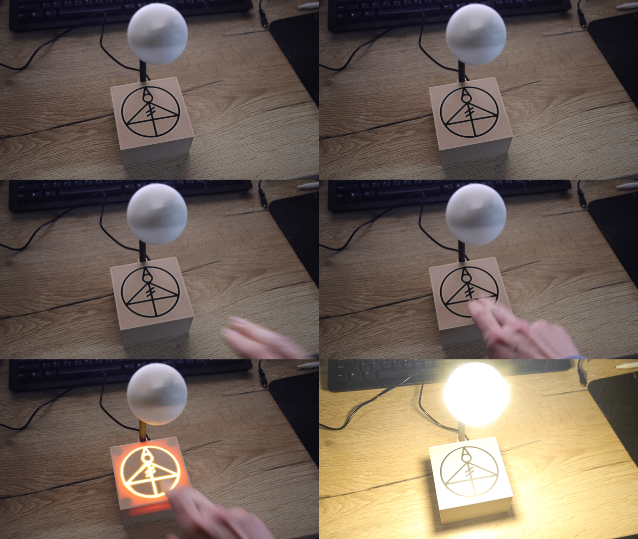
The light glyph lamp is an open-source touch-activated LED lamp based on the light glyph seen in The Owl House.
All source files can be found at [1].


3D printable parts
The exterior parts of the lamp can be 3D printed. FDM is highly recommended for the structural parts, although the orb and diffuser may use resin instead. The STL files and OpenSCAD source code can be found at [2].
Requirements
- FDM 3D printer
- ~150 g of filament
Diffuser and orb:
- ~50 g of translucent white filament
OR
- Resin printer
- ~30 ml of translucent white resin
Glyph:
- ~10 g of translucent dark filament
- Multi-extrusion capability (optional but recommended)
OR
- Translucent dark resin
- Syringe with large-bore (~0.5 mm) needle
- UV torch or laser pointer
- ~10 g of PVA filament
Main parts
The box and tube may be printed with any filament. In the demonstration video's build, colorFabb woodFill is used for the box, and eSUN ePA-CF is used for the tube. The tube can be printed lying on its side, but do not use supports.
The diffuser and orb should be printed in a translucent white filament or resin. In the demonstration video's build, clear eSUN eResin-PLA, dyed with SigWong white alcohol ink is used. Depending on the desired luminosity, the orb may get somewhat hot; in this case, PLA filament may be less suitable.
Faceplate and glyph
Printing the faceplate is somewhat more complex, as it requires two colours. Furthermore, the glyph should have a greater translucency than the other faceplate material, but a darker colour when not backlit. There are several ways to achieve this, two of which are highlighted here.
Pure FDM with multi-extrusion or filament swapping
In this approach, the STLs for the faceplate and the glyph are used. If using Cura as a slicer, set up a multi-extrusion printer, which may be emulated using filament swaps. Load the STLs, and assign each to its own extruder, then combine the models. In PrusaSlicer, first import the faceplate, then right-click and use "add part" to import the glyph. As in Cura, multi-extrusion may be emulated with filament swaps.
Few filaments exist which are dark but translucent. One possibility is the translucent grey PETG by Matterhackers. Although it is generally not recommended to mix filament types in multi-extrusion (as materials with different shrinkage rates tend to separate), the glyph STL contains a "hidden" brim, which allows it to stay mechanically locked to the faceplate even if two different materials are used.
Resin inlay
The resin inlay approach is used in the build shown in the demonstration video. Here, the glyph is not printed, but made manually using resin. This step requires a water-soluble filament such as PVA, a dark-but-translucent 3D resin such as eSUN Hard-Tough black, a syringe with a large-diameter (~0.5 mm inner diameter) needle, and a UV torch or laser pointer.
The STLs to use are the faceplate and the raft. Place the raft on the build plate, and the faceplate on top of it, upside-down, without a gap. In the G-code, insert a filament change (M600) after 0.4 mm. Also insert a pause (M601) or filament change after 1.6 mm.
Start printing the raft using a water-soluble filament such as PVA. At the first M600, switch to the desired material for the faceplate. At the pause, use the syringe to deposit a thin layer of resin, ideally 0.1 mm or less, in the cutout where the glyph should be. Thoroughly cure the resin with the UV torch or laser pointer. N.B. make absolutely sure you obey basic resin safety guidelines, and in particular DO NOT breathe the fumes when curing. Repeat this, in thin layers, until the entire cutout is filled, including the brim. Then resume the print, and when it finishes, again build up the remaining 0.6 mm of the glyph cutout with resin.
Finally, very carefully remove the print—raft and all—from the build plate, and place it in warm water until the raft is fully dissolved. N.B. being too aggressive when removing the print, or peeling off the raft before it has sufficiently dissolved, can cause the resin inlay to crack.
Electronics
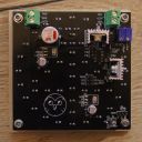
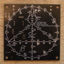
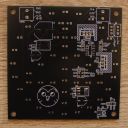
The electronics are designed with gEDA. The gschem and PCB files can be found at [3]. The PCB gerbers can be found at [4]. The PCB is difficult to fabricate at home as it uses plated through-holes and vias with a small drill size; it is recommended to use a service like JLCPCB to manufacture the board (<€10 for 5 copies, including shipping). The gerber zip can be uploaded directly to JLCPCB. The components are all inexpensively available from AliExpress.


Requirements
- Fine-tipped soldering iron (regulated station recommended)
- Needle-nose tweezers
- A steady hand—many components use a 0402 package
- AVR ISP programmer, e.g. AVRISP MKII
- Light glyph PCB
- 2× TO220 heatsink and thermal pads (optional but recommended)—fasten with M3x6 screws
Full BOM:
| Component ID | Package/footprint | Value/part name | AliExpress link |
|---|---|---|---|
| C1 | 0402 | 100 nF | [5] |
| C2 | 0402 | 100 nF | [6] |
| C3 | Pol SMD, 12.5 mm | 1000 µF | [7] |
| C4 | 0603 | 1 µF | [8] |
| C5 | 0402 | 100 nF | [9] |
| C6 | Pol SMD, 6.3 mm | 100 µF | [10] |
| C7 | 0603 | 1 µF | [11] |
| C8 | 0402 | 100 nF | [12] |
| C9 | Pol SMD, 6.3 mm | 100 µF | [13] |
| C10 | 0402 | 10 nF | [14] |
| C11 | 0402 | 10 nF | [15] |
| CS | 0402 | 1.5 nF[a] | [16] |
| CONN1 | Terminal, 5.08 mm pitch | Degson DG129-5.08-02P | [17] |
| CONN2 | None; plated through hole | - | - |
| CONN3 | Terminal, 5.08 mm pitch | Degson DG129-5.08-02P | [18] |
| D1-D48 | Through-hole LED, 3 mm | Warm white | [19] |
| J1 | Header, 2×3, 2.54 mm pitch | Male ISP header | [20] |
| J2 | Header, 1×3, 2.54 mm pitch | Male header | [21] |
| J3 | Header, 1×3, 2.54 mm pitch | Male header | [22] |
| Q1 | TO220W | IRLZ44N | [23] |
| Q2 | TO220W | IRLZ44N | [24] |
| R1 | 0603 | 100 kΩ | [25] |
| R2 | 0603 | 100 kΩ | [26] |
| R3 | 0603 | 10 kΩ | [27] |
| R4 | 3296W trimpot | 10 kΩ | [28] |
| R5 | 3296W trimpot | 10 kΩ | [29] |
| R6-R21 | 0603 | 180 Ω[b] | [30] |
| RS | 0603 | 10 kΩ | [31] |
| U1 | SO14 | ATtiny44A | [32] |
| U2 | SOT23-6 | AT42QT1010 | [33] |
| U3 | SOT223 | AMS1117-5.0 | [34] |
| U4 | SOT223 | AMS1117-5.0 | [35] |
Electronics assembly
Soldering the components is reasonably straight-forward. First solder the SMD resistors (R6-R21) on the front side. Then flip to the back side and solder the SMD components by increasing height, starting with the 0402 capacitors and ending with the 1000 µF capacitor. Attach the heatsinks to the TO220W MOSFETs and place them on the backside (the heatsink aligns with the markings on the board). Then solder the trim potentiometers and the connectors. CONN1 and CONN3. Note that these should both face towards the centre line of the board. Leave CONN2 open for the time being; we will make and connect a sense pad on the glyph later.
Finally, flip to the front side and install the 3 mm LEDs, inserting them up to the "wings" on the pins. Note that the square hole is the cathode, i.e. the short pin of the LEDs. Trim the legs off the LEDs.
Flashing the firmware
The firmware and source code can be found at [36]. To flash it, connect the ISP programmer to the ISP header J1, taking note of the correct orientation. DO NOT connect 12V power; the programmer should power the circuit. N.B. the "Orb BRT" text on the PCB should be ignored at this stage.
Flashing is easily done using AVRDUDE, e.g.
avrdude -p t44 -c avrispmkII -U flash:w:flash.hexSense capacitor
One point of trial and error exists in the sense capacitor, CS. Typically, a value between 1 and 10 nF should be used, with higher values increasing touch sensitivity as well as noise sensitivity. It is highly recommended to have several values within this range available and experiment until you find the best option. Choosing a value that is too small will make the lamp unresponsive to touch, or only sensitive to touch with a full hand. On the other hand, choosing a value that is too large may cause the lamp to oscillate between off and on states.
Assembly
Requirements
- 12V adapter with 5.5 mm × 2.5 mm barrel connector, e.g. [37]
- 12V LED strip, ~30 cm, e.g. [38]
- 5.5 mm × 2.5 barrel connector, female
- ~50 cm each of red and black hookup wire
- ~4 mm diameter and ~10 mm diameter heat shrink tubing (optional but recommended)
- 4× M3x12 screws
- 70 mm copper tape
- 0.3 mm enamelled copper wire
- Silver conductive glue
- Small-tipped hobby knife, e.g. X-Acto
- Multimeter
- Soldering iron
- 4× M3 brass inserts, 5 mm outer diameter
- Hot glue gun
- 2× 2.54 mm header jumper
- Flat-head jeweller's screwdriver
Making the sense pad
On the back side of the face plate, cover everything inside the glyph circle with copper tape, then cut out and remove the glyph lines from the tape using the hobby knife. Hold the faceplate in front of a light and look at it from the front to verify no tape obscures any part of the glyph lines.
Strip the enamel from ~8 cm of the copper wire, and cut the stripped wire into ~1 cm pieces. With the faceplate face-down and the "arrow" of the glyph pointing away from you, start at the copper tape "island" at the lower right, and place the lengths of copper wire across the glyph lines until all islands are connected. There should be a single current path from every island to the one on the lower right; make sure there are no loops. Fix the wires in place with the conductive glue.
Now take around 10 cm of copper wire, and strip the first 2 or 3 centimetres. Bend the stripped end into a zig-zag or spiral, and place it on the lower right island, with the unstripped tail pointing toward the lower-right standoff. Again fix the stripped wire in place with the conductive glue. The glue will not be conductive until it has fully set; this takes several hours, and you should leave the faceplate in a safe location for the full duration. While you wait for the glue to set (it is recommended to leave it overnight), you can assemble the orb and power connector.
Orb assembly
Begin by preparing a ~30 cm length of LED strip. Completely remove the adhesive tape (not just the protective film that covers it), and attach ~35 cm leads using the red and black hookup wires (red on +, black on -). Secure the solder joints with heat shrink tubing (or insulation tape), using just enough to cover the joints. Feed the LED strip into the orb, using a thin, blunt pin or pointy tweezers to manipulate it on the inside, if necessary. Continue until only the leads stick out.
Feed the other end of the leads into the short end of the tube, until they come out of the other end. Gently pull from the long side until you can insert the short side into the orb until you hit the square fins. At this point, you may opt to leave the the tube out of the box to make for easier testing later; in this case, strip around 6 mm of insulation from the ends of the leads. However, if you wish to proceed, insert the remainder of the leads down the channel at the back of the box, and use needle-nose tweezers or pliers to pull them further into the box. Again, gently pull, now inserting the long side of the tube into the channel until you hit the square fins on that side.
If necessary, trim down the leads so about 10 cm is inside the box. Strip around 6 mm of insulation from the ends.
Power connector assembly
Take the female barrel connector and attach ~10 cm black and red leads. The red one (+) should go on the short pin and the black on the long pin (-), although it is a good idea to first connect the 12V adapter and verify the polarity. Optionally insulate the connection with some heat shrink tubing.
At this point, you may wish to leave the connector out of the box to make for easier testing, and install it later. If so, strip around 6 mm of insulation from the ends of the leads. Otherwise, insert the leads from the outside of the box into the small truncated circular hole in the back. Push the barrel connector into the hole, noting the flat sides. From the inside, feed the leads through the nut included with the barrel connector. Fasten the nut onto the connector with your fingers and tighten it with needle-nose pliers. Finally, strip ~6 mm of insulation from the end of the leads.
Faceplate and electronic assembly
Once the conductive glue on the faceplate wires has set, verify electrical continuity across the copper islands with a multimeter, or (les ideally) with a low-power LED indicator. To do so, carefully strip a few millimetres of enamel off the wire "tail" pointing away from the lower-right copper island (lower-left if seen from the front). Probe the resistance/continuity between this stripped end and each of the copper islands. No connection should read more than a few tens of ohms, tops.
Now slide the diffuser over the standoffs. The flat side of the diffuser should face towards the glyph. Insert the brass inserts into the standoff holes and push them in using a soldering iron until they are flush with the surface. Leave them to cool off for a minute or so.
Take the assembled PCB and fix it onto the faceplate with the 4 M3x12 screws. Do not tighten the screws. Ensure that the 3 mm LEDs face towards the diffuser and are aligned with the glyph. The copper wire tail should be close to CONN2 on the PCB. With some needle-nose tweezers, gently feed this copper wire through the CONN2 hole from the LED side. Pull it through the hole until there's around 5 mm of slack against the side of the diffuser. Do not pull hard; the conductive glue is very weak and you may tear it otherwise. Now solder the copper wire onto the CONN2 hole on the component side. You will need to melt through the insulating enamel before you can make an electrical connection, so be patient. Verify the connection between CONN2 and the copper islands on the faceplate, then trim the excess copper wire. (This is important, as it will interfere with the capacitive touch sensor.)
Testing the electronics
Insert the leads for the power jack into the terminal labelled "PWR" and tighten the screws. Note that the ground (black wire) should be closest to the board edge. Then attach the orb leads to the terminal labelled "Orb", noting that the connections are reversed: here, +12 V (red wire) should be closest to the board edge.
Place one of the jumpers across the top pins of J2, labelled "Glyph BRT" (BRT stands for BRightness Test), and the other across the GND and MOSI pins of J1, labelled "Orb BRT". Now connect the 12V adapter to the barrel jack and insert it in the wall socket. If everything is OK, the glyph should light up. You can now use the potentiometer R4, labelled "glyph", to adjust the brightness. Once you are satisfied, remove the Glyph BRT jumper, carefully' so as to not create a short-circuit (you may disconnect power first to eliminate the risk). The glyph should turn off and the orb should turn on. Adjust the brightness until you are satisfied, then remove the Orb BRT jumper.
Now, all LEDs should be off, and the lamp will enter idle mode. At this point, touching the front of the glyph should cause it to light up briefly, after which the orb turns on, as in the demonstration video. If it does not, it usually means the value of CS is too low; see "Sense capacitor" in the previous section. However, if increasing CS does not make the lamp responsive to touch, you can try touching the wire stub at CONN2 directly (make sure your hands are dry). If this does turn the lamp on, it means the copper tape on the glyph is not properly connected to CONN2. If it still does not turn on when touching CONN2 while having a large (≥ 10 nF) CS, you have most likely damaged U2 (the touch sensor, not the band) or another component when soldering.
Finishing up
Once the electronics work as desired, disconnect power and use some hot glue around the corners of the PCB to secure it gently to the faceplate and diffuser. Use only a small drop; you do not want to cover any electronic components or get glue in the screw threads. It should be easy to peel off at a later stage, if desired.
Now remove the M3x12 screws holding the board in place. At this stage, make sure the BRT jumpers are removed! Then turn the assembly over and place it in the box. Insert the M3x12 screws from the bottom side of the box and gently tighten them. Take care not to over-tighten, particularly if you used woodFill, as this is a weak filament and can easily be damaged by twisting.
Finally, reconnect power. You should see the glyph and orb flash briefly, in sequence, and then turn off. Ensure the lamp properly responds to touch. Congratulations, you're done, hoot hoot!
Troubleshooting and notes
Occasionally, the lamp may start oscillating between states. In the current version, this can sometimes be stopped by pushing down on the glyph with a full hand or by grabbing the box from the sides, but the only sure-fire way to stop it is to temporarily disconnect power. This will hopefully be eliminated in a future revision by letting the microcontroller reset the touch sensor. In the mean time, use the smallest possible value for CS that you can get away with to minimise the failure rate.
For advanced users, the current revision of the board allows you to use an external trigger signal, e.g. from a TTP223 board. To do so, remove the AT42QT1010 (U2) and attach the external board to the TRIG pin CONN4. In the default configuration, the external trigger should be an active-high push-pull output. To use an active-low signal, define TRIG_ACTIVE_LOW in the firmware. To use an open-drain trigger signal, remove R3 and define TRIG_OPEN_DRAIN in the firmware.